CCIE Lab - BGP
CCIE Lab - BGP
type: Post
status: Published
date: 2026/03/09
slug: CCIE-Lab-BGP
summary: This blog records my BGP lab experiments during my CCIE study process.
tags: Cisco, Experiment, Router
category: Knowledge
CCIE BGP Lab Notes
This blog records my BGP lab experiments during my CCIE study process.
In this section, I will document all BGP-related labs in detail, including the network topology, configuration steps, verification commands, debugging outputs, and routing behavior analysis.
Each lab will focus on a specific BGP scenario and will include the complete configuration of all devices as well as the command outputs used to verify the results.
The goal is to build a structured record of practical BGP experiments and observations throughout the CCIE learning journey.
Lab 1 - Basic eBGP Peering
1 Topology
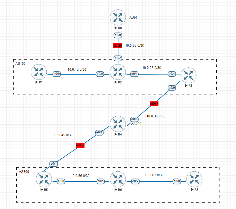
In this first lab, we build the most basic eBGP peering between two routers.
The topology consists of two routers directly connected through an Ethernet link.
Network design:
| Device | AS | Loopback | Interface |
|---|---|---|---|
| R1 | AS100 | 1.1.1.1/32 | 10.0.12.1 |
| R2 | AS200 | 2.2.2.2/32 | 10.0.12.2 |
Key design points:
- Each router owns a loopback address
- The loopback is used as the BGP Router ID
- The routers are directly connected via Ethernet0/0
- The link network is 10.0.12.0/30
2 Verify Physical Connectivity
Before configuring BGP, we first verify that the directly connected link is reachable.
R1 pings R2's interface address.
Router# ping 10.0.12.2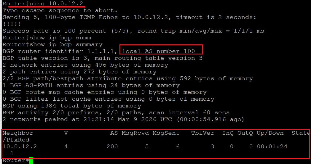
Output:
- Success rate 100%
- Round-trip latency minimal
This confirms that the Layer-3 connectivity between the routers is working properly.
Only after IP connectivity is confirmed should BGP be configured.
3 Establish BGP Peering
Once BGP is configured, we can verify the session using:
show ip bgp summary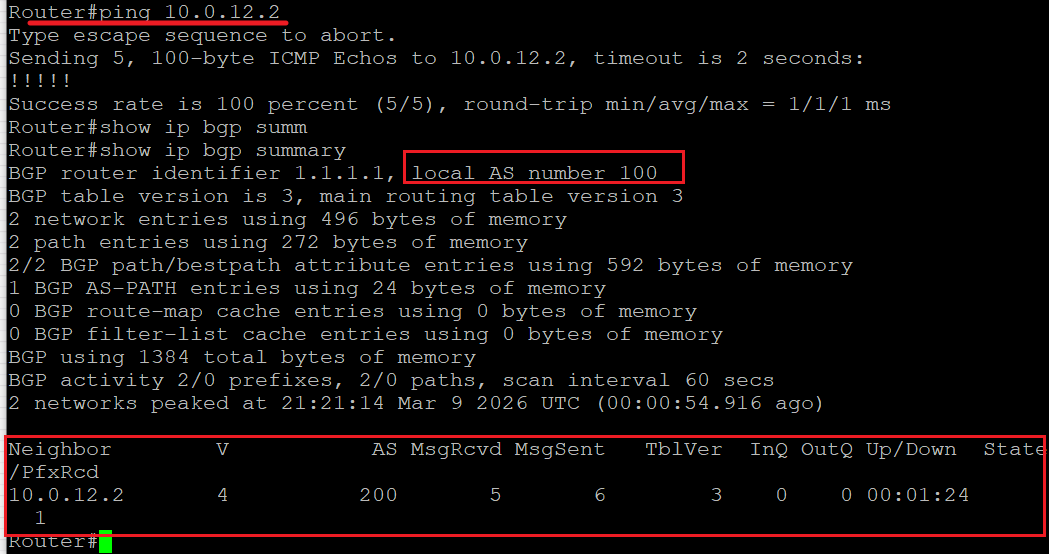
Important information shown here:
- Router ID: 1.1.1.1
- Local AS: 100
- Neighbor: 10.0.12.2
- Remote AS: 200
The table also displays:
| Field | Meaning |
|---|---|
| MsgRcvd | BGP messages received |
| MsgSent | BGP messages sent |
| Up/Down | Duration of the BGP session |
| State/PfxRcd | Number of prefixes received |
If the State column shows a number instead of "Idle/Active", it means the BGP session is successfully established.
In this case, the neighbor relationship between AS100 and AS200 is already working.
4 Inspect the BGP Table
We can view the full BGP table with:
show ip bgpExample output:
Network          Next Hop      Metric LocPrf Weight Path
1.1.1.1/32       0.0.0.0              0      32768 i
2.2.2.2/32       10.0.12.2            0      0     200 i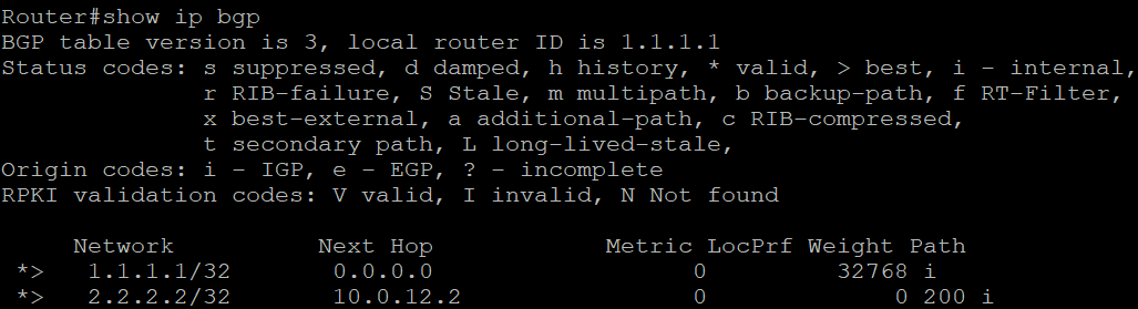
Explanation:
| Field | Meaning |
|---|---|
| Network | Advertised prefix |
| Next Hop | Next hop toward the prefix |
| Weight | Cisco proprietary attribute |
| Path | AS-Path |
i | Origin = IGP |
5 Verify the Routing Table
Next we verify that the route learned from BGP has been installed into the routing table.
show ip routeExample entry:
B 2.2.2.2 [20/0] via 10.0.12.2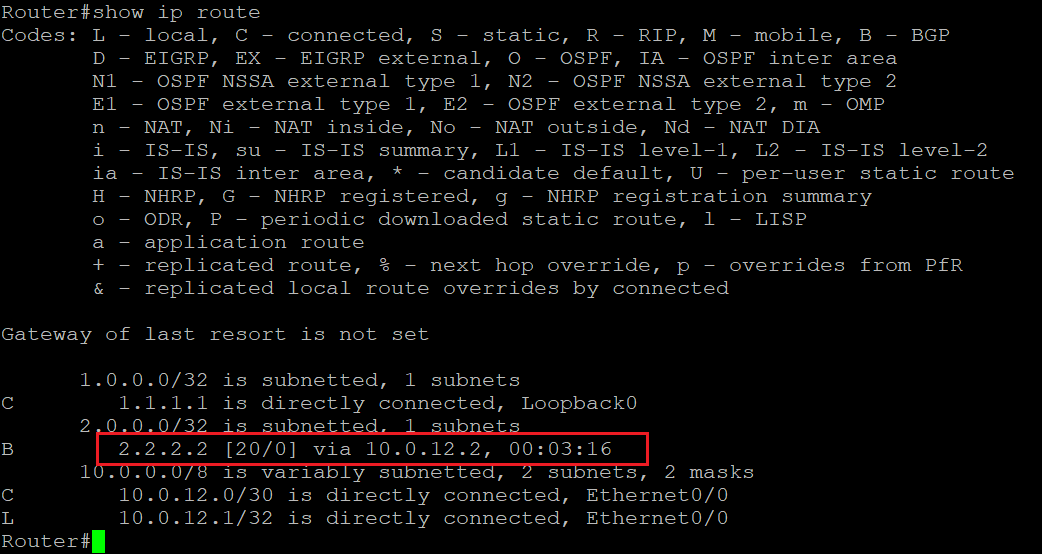
Explanation:
| Field | Meaning |
|---|---|
| B | Route learned via BGP |
| 20 | Administrative Distance (eBGP) |
| 0 | Metric |
| via 10.0.12.2 | Next hop |
This confirms that the 2.2.2.2/32 network learned through BGP has been successfully installed into the RIB.
6 End-to-End Connectivity Test
Finally we verify end-to-end connectivity using the loopback interfaces.
ping 2.2.2.2 source 1.1.1.1Result:
Success rate is 100 percent
This proves that:
- BGP route exchange is working
- The route is installed in the routing table
- Traffic forwarding is functioning correctly
7 Device Configuration
R1 Configuration
enable
configure terminal

interface Ethernet0/0
 ip address 10.0.12.1 255.255.255.252
 no shutdown

interface Loopback0
 ip address 1.1.1.1 255.255.255.255

router bgp 100
 bgp router-id 1.1.1.1
 neighbor 10.0.12.2 remote-as 200
 network 1.1.1.1 mask 255.255.255.255
R2 Configuration
enable
configure terminal

interface Ethernet0/0
 ip address 10.0.12.2 255.255.255.252
 no shutdown

interface Loopback0
 ip address 2.2.2.2 255.255.255.255

router bgp 200
 bgp router-id 2.2.2.2
 neighbor 10.0.12.1 remote-as 100
 network 2.2.2.2 mask 255.255.255.255
Lab 2 - IGP Foundation and iBGP Full Mesh
Topology
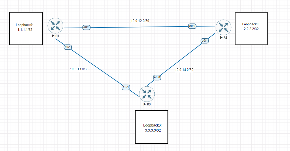
In this lab, three routers are connected in a triangular topology.
All routers belong to the same autonomous system AS100, and OSPF is used as the IGP to provide reachability between loopback interfaces.
Loopback addresses:
| Router | Loopback |
|---|---|
| R1 | 1.1.1.1 |
| R2 | 2.2.2.2 |
| R3 | 3.3.3.3 |
The physical links are:
- R1-R2 -> 10.0.12.0/30
- R1-R3 -> 10.0.13.0/30
- R2-R3 -> 10.0.14.0/30
IGP Configuration
First, OSPF is configured on all routers to ensure full IP reachability.
router ospf1
 network0.0.0.0255.255.255.255 area0
This command enables OSPF on all interfaces of the router.
After configuration, the OSPF neighbors should reach the FULL state.
This confirms that all routers have established OSPF adjacency and the loopback addresses are reachable through the IGP.
iBGP Configuration
Next, iBGP is configured between the three routers.
Since all routers are in AS100, they establish iBGP sessions using their loopback interfaces.
Example configuration on R2:
router bgp100
 bgp router-id2.2.2.2
 neighbor1.1.1.1 remote-as100
 neighbor1.1.1.1 update-source Loopback0
 neighbor3.3.3.3 remote-as100
 neighbor3.3.3.3 update-source Loopback0
All three routers must form a full mesh iBGP topology.
Verification:
show ip bgp summaryExample output shows that the BGP sessions have been successfully established.
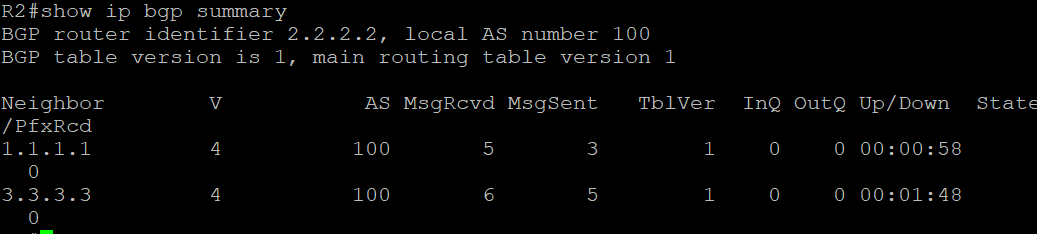
At this stage:
- iBGP adjacency is established
- IGP provides loopback reachability
- The control plane connectivity is verified
Base Configuration
Example configuration for R1:
interface Loopback0
 ip address1.1.1.1255.255.255.255

router ospf1
 network0.0.0.0255.255.255.255 area0

router bgp100
 bgp router-id1.1.1.1
 neighbor2.2.2.2 remote-as100
 neighbor2.2.2.2 update-source Loopback0
 neighbor3.3.3.3 remote-as100
 neighbor3.3.3.3 update-source Loopback0
The other routers follow the same configuration logic.
Lab 3 - eBGP Multihop with Loopback Peering
Topology
In this lab, the topology is modified.
R2 is used only as a transit router, while R1 and R3 establish an eBGP session using their loopback interfaces.

Network addressing:
| Link | Network |
|---|---|
| R1-R2 | 10.0.13.0/30 |
| R2-R3 | 10.0.14.0/30 |
Loopbacks:
| Router | Loopback |
|---|---|
| R1 | 1.1.1.1 |
| R3 | 3.3.3.3 |
AS planning:
| Router | AS |
|---|---|
| R1 | AS100 |
| R3 | AS200 |
| R2 | Transit only |
Static Routing
Since BGP neighbors use loopback addresses, reachability must be ensured through static routing.
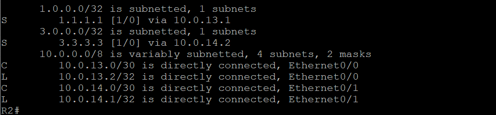
Example configuration on R2:
ip route 1.1.1.1 255.255.255.255 10.0.13.1
ip route 3.3.3.3 255.255.255.255 10.0.14.2
This allows R2 to forward traffic between the loopback networks.
Example routing table:

eBGP Configuration
R1 configuration:
router bgp 100
 bgp router-id 1.1.1.1
 neighbor 3.3.3.3 remote-as 200
 neighbor 3.3.3.3 ebgp-multihop 2
 neighbor 3.3.3.3 update-source Loopback0
 network 1.1.1.1 mask 255.255.255.255
R3 configuration:
router bgp 200
 bgp router-id 3.3.3.3
 neighbor 1.1.1.1 remote-as 100
 neighbor 1.1.1.1 ebgp-multihop 2
 neighbor 1.1.1.1 update-source Loopback0
 network 3.3.3.3 mask 255.255.255.255
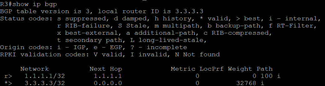
After configuration, verify that the BGP session is established.
show ip bgp summary
Advertising Additional Networks
After confirming the eBGP session is working, new loopback interfaces are added.
R1:
interface Loopback1
 ip address 11.11.11.11 255.255.255.255
R3:
interface Loopback1
 ip address 33.33.33.33 255.255.255.255
These networks are then advertised through BGP.
R1:
network 11.11.11.11 mask 255.255.255.255R3:
network 33.33.33.33 mask 255.255.255.255
BGP Table Verification
After the new routes are advertised, both routers should learn the remote network through BGP.
show ip bgp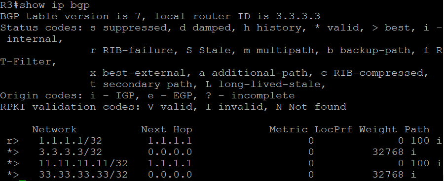
Example observation:
>indicates the best path
Next Hopshows the BGP next hop
AS Pathdisplays the AS sequence
Routing Table Verification
Finally, verify that the BGP-learned routes are installed into the routing table.
show ip route
Example entry:
B 33.33.33.33/32 [20/0] via 3.3.3.3This confirms that the route has been successfully learned through BGP and installed in the routing table.
Lab 4 - BGP Route Advertisement, Next-Hop Behavior, and Route Aggregation
Topology

In this lab, four routers are connected in a linear topology to validate multiple BGP behaviors within a single scenario.
The topology combines eBGP and iBGP relationships:
- R1 -> R2 -> eBGP (AS100 -> AS200)
- R2 -> R3 -> iBGP (AS200)
- R3 -> R4 -> eBGP (AS200 -> AS300)
This design allows us to verify:
- Route advertisement using
network
- Route advertisement using
redistribute
- Default iBGP next-hop behavior
- The effect of
next-hop-self
- Route aggregation and summarization
Network Overview
| Device | AS | Loopback | Interfaces |
|---|---|---|---|
| R1 | AS100 | 1.1.1.1/32 | 10.0.13.1 |
| R2 | AS200 | 2.2.2.2/32 | 10.0.13.2 / 10.0.14.1 |
| R3 | AS200 | 3.3.3.3/32 | 10.0.14.2 / 10.0.15.1 |
| R4 | AS300 | 4.4.4.4/32 | 10.0.15.2 |
| Link | Network |
|---|---|
| R1-R2 | 10.0.13.0/30 |
| R2-R3 | 10.0.14.0/30 |
| R3-R4 | 10.0.15.0/30 |
Base BGP Configuration
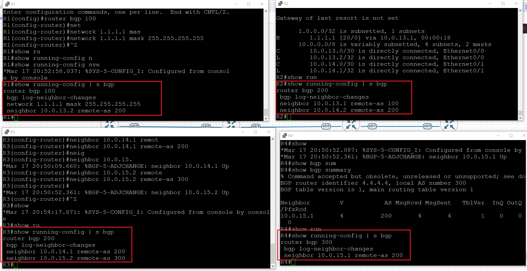
R1
router bgp 100
 neighbor 10.0.13.2 remote-as 200
R2
router bgp 200
 neighbor 10.0.13.1 remote-as 100
 neighbor 10.0.14.2 remote-as 200
R3
router bgp 200
 neighbor 10.0.14.1 remote-as 200
 neighbor 10.0.15.2 remote-as 300
R4
router bgp 300
 neighbor 10.0.15.1 remote-as 200
At this stage:
- All BGP neighbors are established
- Control plane connectivity is verified
Route Advertisement with network
Configuration (R1)
router bgp 100
 network 1.1.1.1 mask 255.255.255.255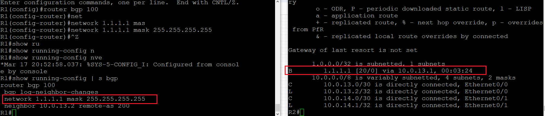
Verification (R2)
show ip bgp
show ip route
Observation
- Route
1.1.1.1/32is received from R1
- Next-hop =
10.0.13.1
- Origin =
i(IGP)
- Route is installed in routing table
Key Point
network:
- Requires the prefix to already exist in local routing table
- Provides precise and controlled route advertisement
Route Advertisement with redistribute connected
Configuration (R4)
router bgp 300
 redistribute connected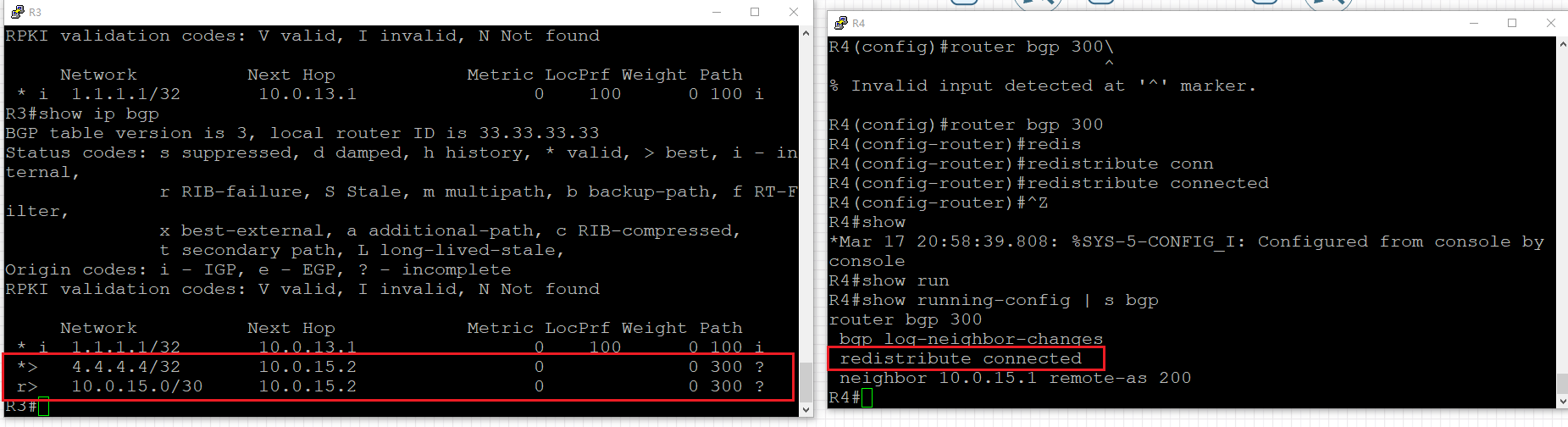
Verification (R3)
show ip bgpObservation
Routes received from R4:
- 4.4.4.4/32
- 10.0.15.0/30
Attributes:
- Origin =
?(incomplete)
Key Point
redistribute connected:
- Injects all connected routes into BGP
- Less controlled than
network
- May introduce unnecessary prefixes
iBGP Next-Hop Behavior
By default:
- eBGP learned routes keep the original next hop when advertised to iBGP
Scenario
- R2 learns route from R1 (eBGP)
- R2 advertises to R3 (iBGP)
Verification (R3)
show ip bgp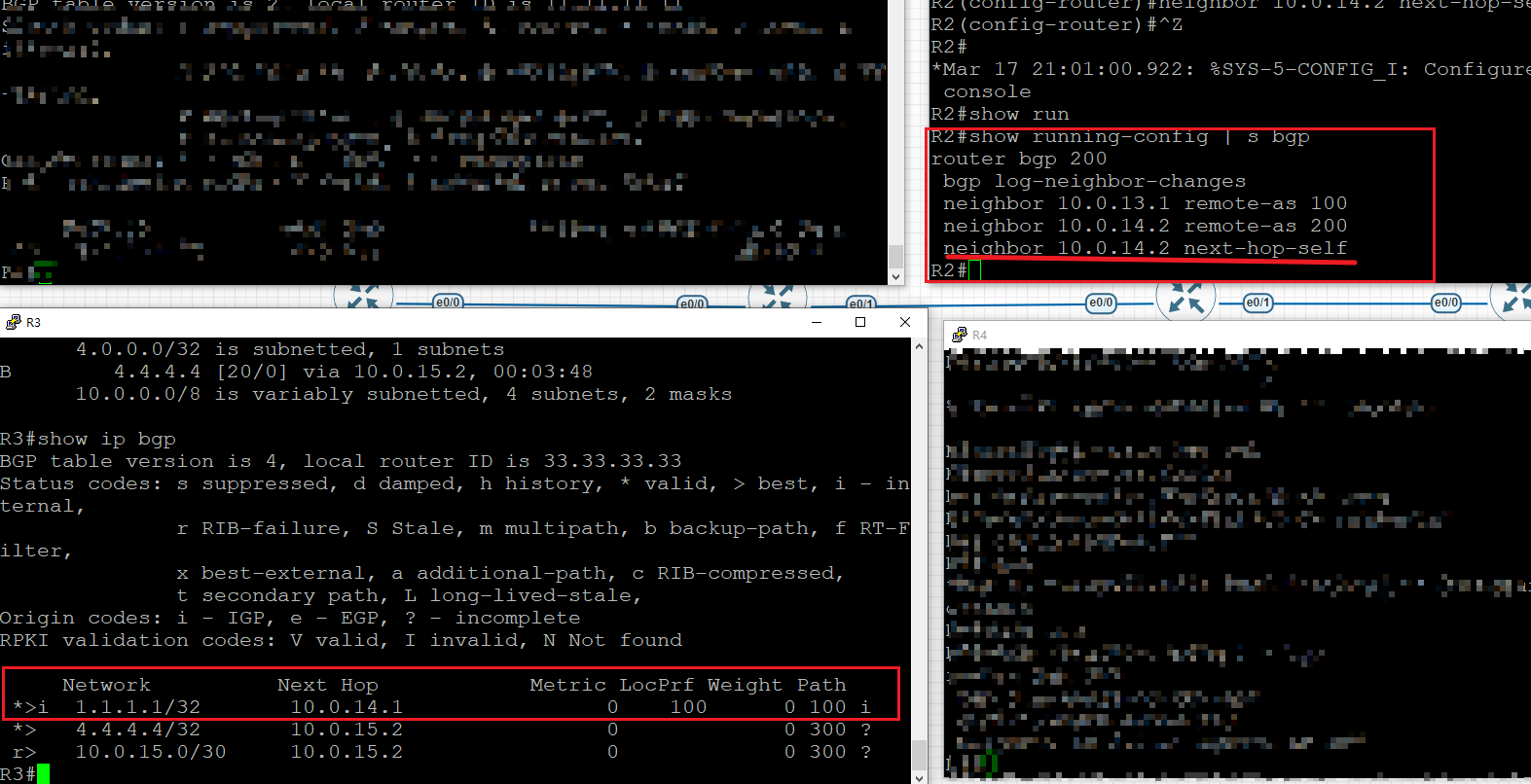
Observation
- Next-hop =
10.0.13.1(R1)
- Not changed to R2
Problem
If R3 cannot reach 10.0.13.1:
- Route exists in BGP table
- But not installed in routing table
Fixing Next-Hop with next-hop-self
Configuration (R2)
router bgp 200
 neighbor 10.0.14.2 next-hop-self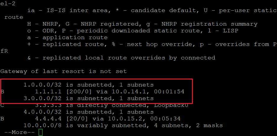
Verification (R3)
show ip bgp
show ip route
Observation
- Next-hop changes to
10.0.14.1(R2)
- Route becomes reachable
- Installed into routing table
Key Point
next-hop-self:
- Forces router to advertise itself as next-hop
- Solves iBGP reachability issues
BGP Route Aggregation
Configuration (R1)
router bgp 100
 network 10.1.0.0 mask 255.255.255.0
 network 10.1.1.0 mask 255.255.255.0
 network 10.1.2.0 mask 255.255.255.0
 network 10.1.3.0 mask 255.255.255.0

 aggregate-address 10.1.0.0 255.255.252.0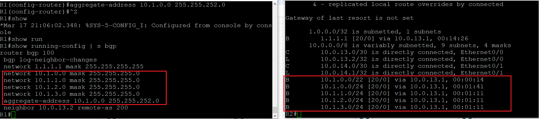
Verification
show ip bgpObservation
- Aggregate route: 10.1.0.0/22
- Specific routes still present:
- 10.1.0.0/24
- 10.1.1.0/24
- 10.1.2.0/24
- 10.1.3.0/24
Key Point
Default behavior:
- Both summary and specific routes are advertised
Suppressing Specific Routes with summary-only
Configuration (R1)
router bgp 100
 aggregate-address 10.1.0.0 255.255.252.0 summary-only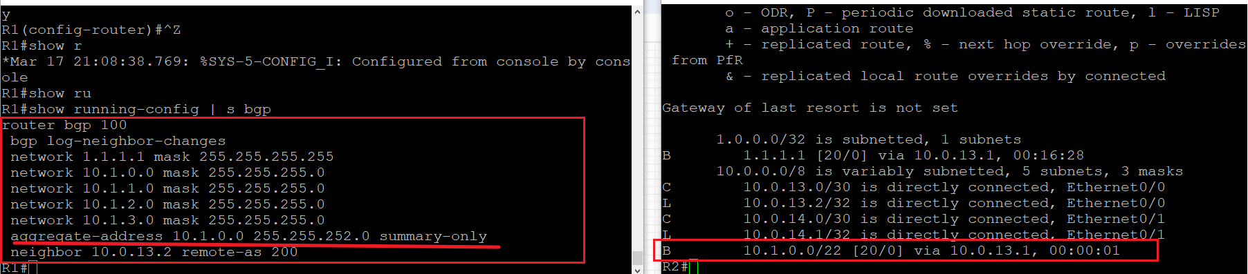
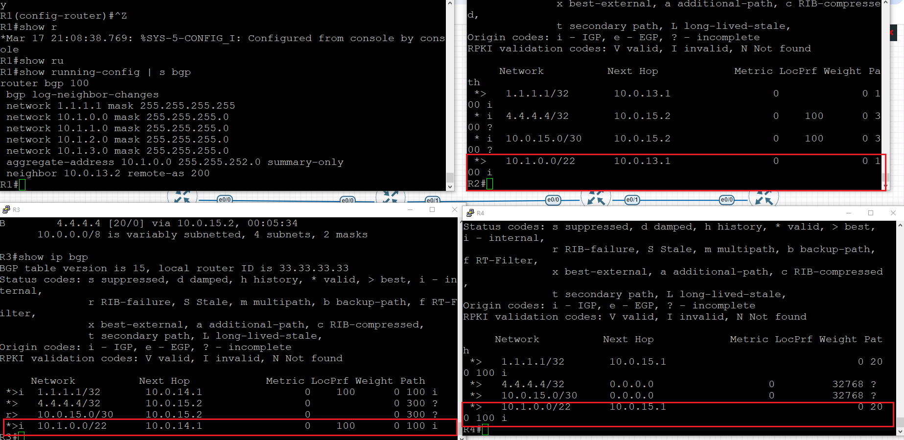
Verification
show ip bgpObservation
- Only aggregate route is advertised:
- 10.1.0.0/22
- Specific routes are suppressed
- May appear with
sflag
Key Point
summary-only:
- Suppresses more specific routes
- Reduces routing table size
- Improves scalability
Lab5: BGP State Machine and Route Advertisement Principles Lab
Topology and Goals
This lab uses a four-AS topology to verify core BGP behavior. AS50 contains R8, AS100 contains R1, R2, and R3, AS200 contains R4, and AS300 contains R5, R6, and R7. The topology is designed to demonstrate the BGP state machine, the meaning of the State/PfxRcd column in show ip bgp summary, best path selection, and iBGP split horizon.
The target is straightforward: first bring up all BGP neighbors, then inject 8.8.8.8/32 from both R6 and R7, verify that R5 learns two candidate paths but selects only one as best, confirm that the route propagates into AS200 and AS100, and finally show that an iBGP-learned route is not re-advertised to another iBGP peer.
Figure 1 - Topology

As shown in Figure 1, the physical links are arranged like this: R8-R2, R1-R2, R2-R3, R3-R4, R4-R5, R5-R6, and R6-R7. In this lab, the BGP relationships are:
- eBGP: R8-R2, R3-R4, R4-R5
- iBGP inside AS100: R1-R2, R2-R3, R1-R3
- AS300: R5-R6, R5-R7
Below is the full IP addressing used in the lab.
- R8 e0/0:
10.0.82.1/30
- R2 e0/2:
10.0.82.2/30
- R1 e0/0:
10.0.12.1/30
- R2 e0/0:
10.0.12.2/30
- R2 e0/1:
10.0.23.1/30
- R3 e0/1:
10.0.23.2/30
- R3 e0/0:
10.0.34.1/30
- R4 e0/0:
10.0.34.2/30
- R4 e0/1:
10.0.45.1/30
- R5 e0/1:
10.0.45.2/30
- R5 e0/0:
10.0.56.1/30
- R6 e0/1:
10.0.56.2/30
- R6 e0/2:
10.0.67.1/30
- R7 e0/0:
10.0.67.2/30
Figure 2 and Figure 4 - All BGP Neighbors Established
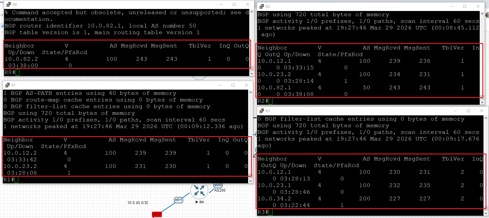
BGP summary R8, R1-R3
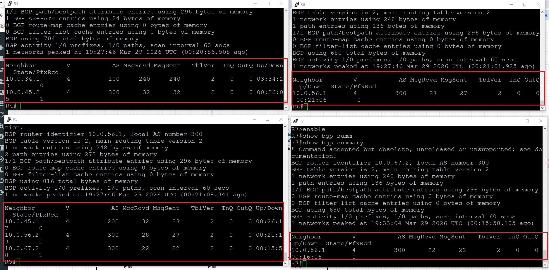
BGP summary R4-R7
Figure 2 and Figure 4 show that all required BGP sessions were successfully established. In Cisco IOS, a BGP session is operational only after the peer reaches Established, and IPv4 route exchange is enabled by default once the neighbor is configured with neighbor x.x.x.x remote-as y unless that behavior is explicitly disabled.
The outputs confirm that the designed eBGP and iBGP relationships are all working. In particular, AS100 has a triangle of iBGP peers, and AS300 allows R5 to learn the same prefix from both R6 and R7, which is the key setup for the later best-path test.
Figure 3 - Understanding State/PfxRcd
Figure 3 focuses on the State/PfxRcd column of show ip bgp summary. This column is one of the fastest ways to understand whether a BGP session is still forming or already exchanging routes.
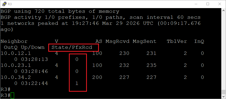
BGP has six states: Idle, Connect, Active, OpenSent, OpenConfirm, and Established. If the session is still coming up, the State/PfxRcd field displays a state name such as Active or Connect. Once the session reaches Established, this field changes to a number, and that number indicates how many prefixes have been received from the neighbor.
In this lab, the numbers in Figure 3 are meaningful:
- On R3, neighbors R1 and R2 show 0, which means the iBGP sessions are up but no useful BGP prefixes are being received from them.
- On R3, neighbor R4 shows 1, which means one prefix is being received from AS200.
- On R4, R2 shows 0 and R6 shows 1, meaning the session to R2 is established but no prefix is currently learned from that side, while one prefix is learned from AS300.
- On R5, both R6 and R7 show 1, which means R5 receives one
8.8.8.8/32path from each router.
The verification command is:
show ip bgp summary
Figure 5 - Injecting 8.8.8.8/32 from R6 and R7
As shown in Figure 5, both R6 and R7 were configured with a static route for 8.8.8.8/32 pointing to Null0. This is required because on Cisco IOS, the BGP network command only advertises a route if that exact prefix already exists in the local routing table.
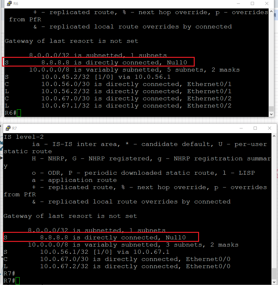
Then both routers advertised the prefix into BGP:
`ip route 8.8.8.8 255.255.255.255 Null0
router bgp 300
network 8.8.8.8 mask 255.255.255.255`
In this part of the lab, there is no route-loop concern between R6 and R7 for the test prefix. Each router originates its own local route, and both of them only need to advertise that prefix toward R5 so that R5 can compare two candidate BGP paths.6-r5-show-ip-bgp.jpg+1
Figure 6 - Two Routes on R5 and One Best Path
Figure 6 shows the BGP table on R5 after both R6 and R7 advertise 8.8.8.8/32. R5 now has two candidate paths to the same destination, one with next hop 10.0.67.2 and one with next hop 10.0.56.2.
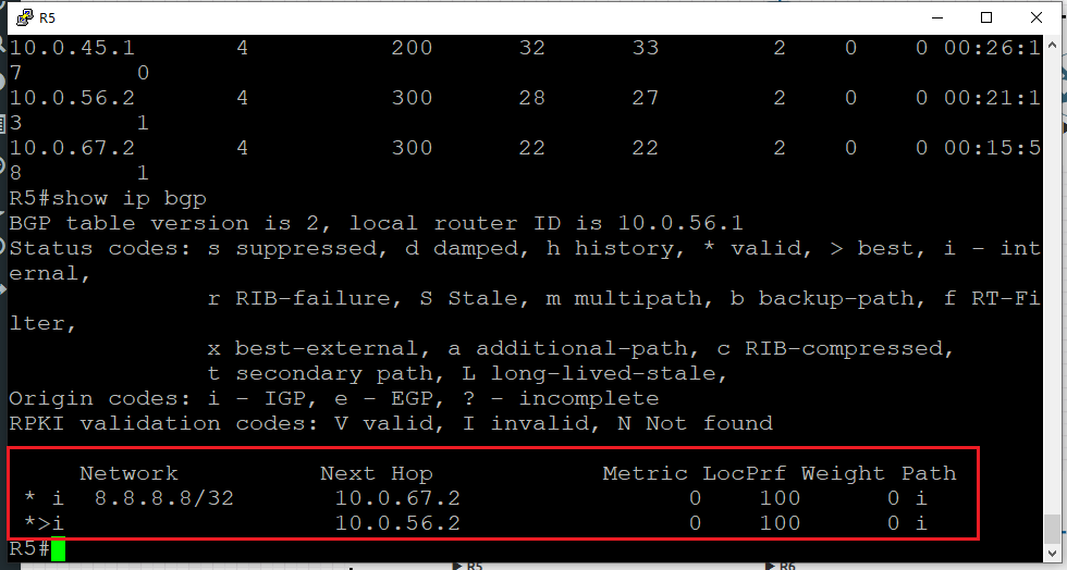
The key observation is the > symbol in front of one of the entries. In Cisco show ip bgp, * means the path is valid, and > means it is the best path selected by BGP. In this lab, the path learned from R6 is marked as best, which demonstrates the principle that BGP may learn multiple routes to the same prefix but, by default, only installs and advertises one best path.
The verification command is:
show ip bgp
Figure 7 - Route Propagation into AS200 and AS100
As shown in Figure 7, the prefix 8.8.8.8/32 is learned by routers in both AS200 and AS100. R4 learns the route from AS300, and then routers in AS100 receive the route through the upstream propagation path.
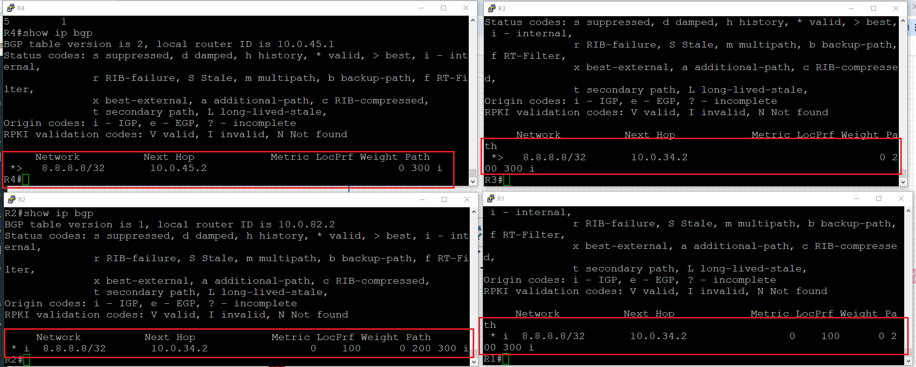
This verifies that the route successfully travels across the topology: AS300 -> AS200 -> AS100. It also reinforces the previous point: downstream ASes do not receive all candidate paths from R5, but only the path selected as the best path. It also reinforces the previous point: downstream ASes do not receive all candidate paths from R5, but only the path selected as the best path.
The verification command is still:
show ip bgp
Figure 8 - iBGP Split Horizon
Figure 8 is the final proof of iBGP split horizon. In this lab, R3 advertises routes such as 1.1.1.1/32 to both R1 and R2, and it is therefore correct that both routers learn the route in their BGP tables. This part is often misunderstood: iBGP absolutely can distribute locally originated or eBGP-learned routes to other iBGP peers.
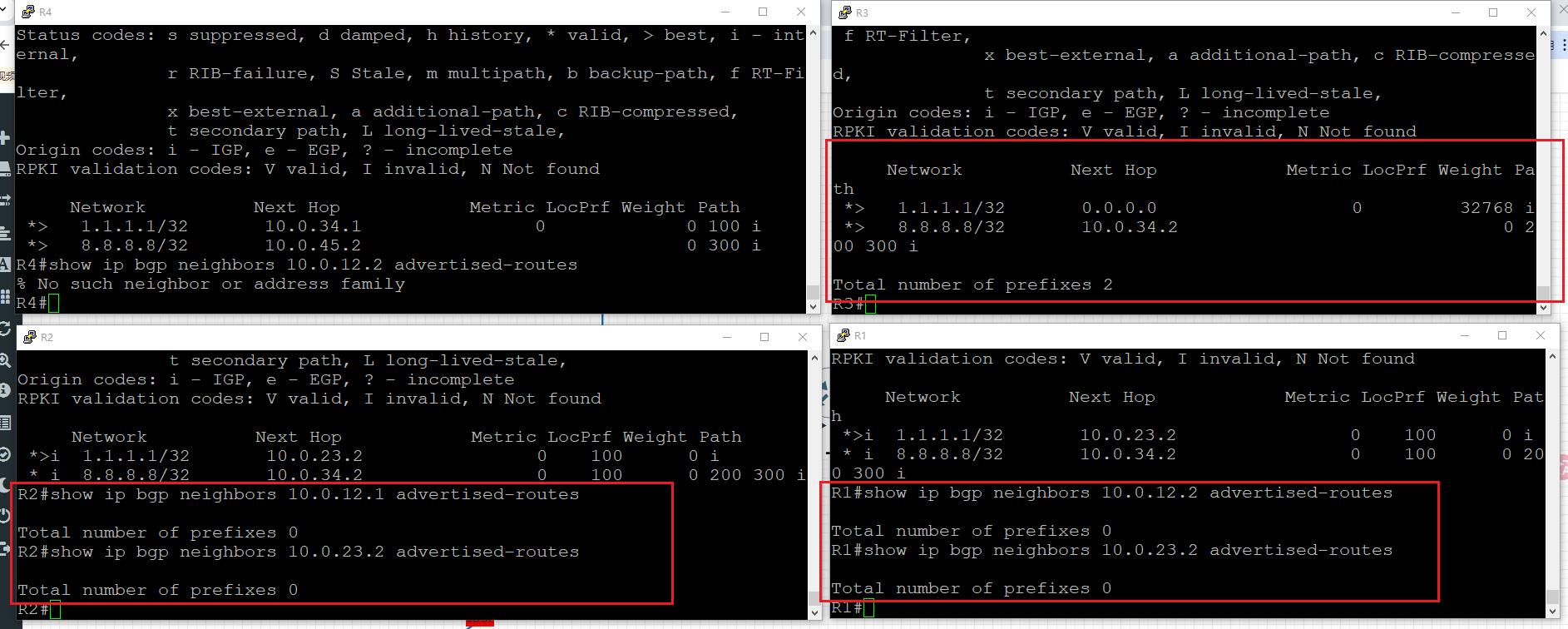
What iBGP does not allow by default is this: a router must not take a route learned from one iBGP peer and advertise it to another iBGP peer. In the screenshot, both R1 and R2 show:
show ip bgp neighbors ... advertised-routes
- Total number of prefixes 0
But shows on R3 that it advertised total 2 prefixes.
That result proves the iBGP-learned routes are not being re-advertised onward inside AS100. This is exactly the iBGP split-horizon rule, and it is one of the core loop-prevention mechanisms in internal BGP design.
Full Verification Commands
For completeness, these are the main commands used in the lab to verify the expected BGP behavior:
`show ip bgp summary
show ip bgp
show ip route
show ip bgp neighbors <neighbor-ip> advertised-routes`
Final Notes
This lab clearly shows the full BGP workflow from neighbor establishment to route propagation. The State/PfxRcd field in show ip bgp summary tells whether a session is still negotiating or already established, and once the session is up, the number in that field represents the number of learned prefixes.
It also demonstrates that BGP does not advertise every path it knows. R5 learns two copies of 8.8.8.8/32, but only one is chosen as the best path and forwarded further. Finally, Figure 8 confirms that inside iBGP, routes learned from one iBGP neighbor are not sent to another iBGP neighbor, which is the essence of iBGP split horizon and the reason it helps prevent routing loops.