M-LAG Lab Case
M-Lag lab case
type: Post
status: Published
date: 2026/02/18
slug: tech-m-lag1
summary: This lab demonstrates the complete deployment process of an M-LAG-based dual-core architecture in a campus network scenario.
tags: Experiment, H3C, Switch
category: Technology
M-LAG Lab
IRF vs M-LAG - Key Differences
Before diving into the lab, it is helpful to understand why M-LAG is chosen over IRF (Intelligent Resilient Framework) in certain scenarios. Both technologies achieve multi-device redundancy and simplified management, but they differ significantly in architecture, requirements, and operational behavior.
| Item | IRF | M-LAG |
|---|---|---|
| Control Plane | Unified - member devices share a single control plane for central management; all forwarding entries are synchronized across members | Separate - each member device maintains its own control plane; only key entries (MAC, ARP, ND) are synchronized |
| Hardware Requirements | Member devices must use the same chip architecture and belong to the same product series | Member devices can be different models - cross-model deployment is supported |
| Software Requirements | All member devices must run the same software version | Some models can run different software versions; full cross-version support is planned for future releases |
| Software Upgrade | Devices can be upgraded simultaneously or separately (separate upgrade is complex); service interruption >30 seconds for traditional master/subordinate switchover; ~2 seconds with ISSU | Devices are upgraded separately; service interruption is less than 1 second; if GIR (Graceful Insertion and Removal) is supported, upgrades do not interrupt services |
| Management | Configured and managed in a unified manner as a single logical device; single points of failure may occur when a controller manages the IRF system | Each device is configured separately; configuration consistency check is available to detect inconsistencies; no single point of failure when managed by a controller |
When to choose M-LAG over IRF: M-LAG is preferred when cross-model or cross-version hardware is involved, when non-stop upgrade (GIR) is a hard requirement, or when the network design requires independent control planes for better fault isolation.
Lab Topology
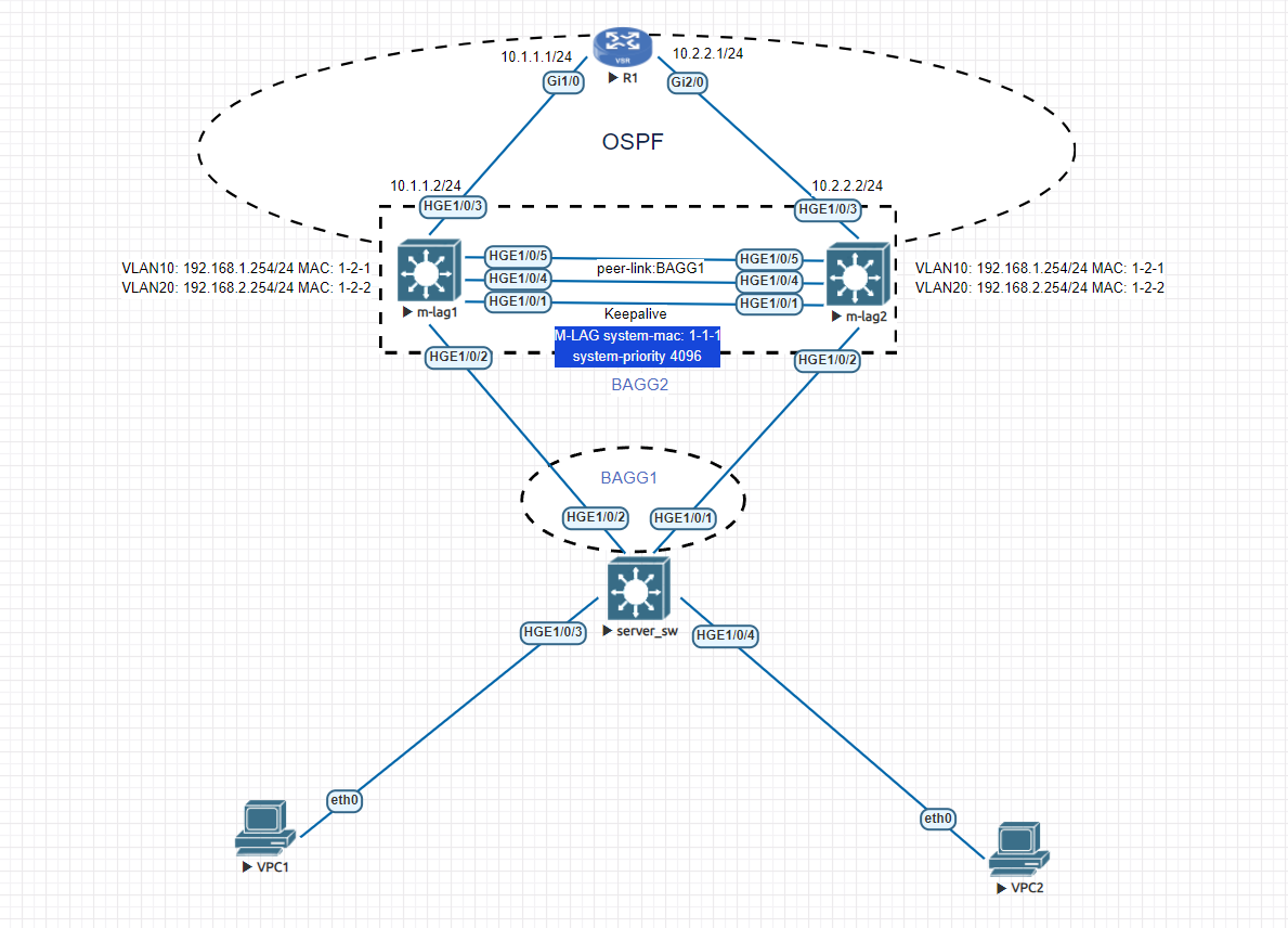
This lab demonstrates the complete deployment process of an M-LAG-based dual-core architecture in a campus network scenario.
Two core switches (SW1 and SW2) are configured to form an M-LAG system,
The lab verifies the following key technical components:
- M-LAG system establishment (System MAC, System Number, Keepalive, MAD exclusion)
- Peer-link configuration and status verification
- Cross-device dynamic link aggregation
- Identical Layer 3 SVI configuration (same MAC and IP on both cores)
- Upstream routing via OSPF toward R1
- End-to-end connectivity validation
By assigning identical MAC and IP addresses to the VLAN interfaces on SW1 and SW2, both devices operate as an active-active distributed gateway. Traffic forwarding remains uninterrupted even if one core switch fails, ensuring high availability.
The final connectivity test confirms:
- PCs can successfully reach their default gateway
- PCs can access the upstream router R1
- The routing domain is fully operational
Lab Environment
This lab is built and tested in EVE-NG (Emulated Virtual Environment - Next Generation).
The switching platform used in the simulation is:
- H3C vS9800 virtual switch
EVE-NG provides a flexible and powerful network emulation platform, allowing realistic simulation of enterprise-grade architectures such as:
- M-LAG
- OSPF routing
- Layer 2 / Layer 3 integration
- Distributed gateway deployment
The entire topology, device interconnection, and protocol behavior were validated within the EVE-NG environment, ensuring that the configuration logic can be reproduced in real production networks.
Lab Requirements
- SW3 acts as the access switch.
- It connects to PC5 in VLAN 10.
- It connects to PC6 in VLAN 20.
- It has dual uplinks to two core switches.
- SW1 and SW2 act as core switches.
- Configure M-LAG between SW1 and SW2.
- Serve as Layer 3 gateways for VLAN 10 and VLAN 20.
- Use cross-device aggregation to connect downstream to SW3.
- No M-LAG is configured on the uplinks.
- Each connects separately to router R1 through two independent links.
Lab Solution
On SW3, create VLAN 10 and VLAN 20.
Configure the interfaces connected to PC5 and PC6 as Access ports in VLAN 10 and VLAN 20 respectively. (Steps omitted)
Configure IP addresses and gateways for the PCs. (Steps omitted)
Configure SW1 and SW2 to Form an M-LAG System
Step 1: Configure SW1 System Parameters
Set SW1 system MAC to 1-1-1, system number to 1, and priority to 4096.
[SW1]m-lag system-mac 1-1-1
[SW1]m-lag system-number 1
[SW1]m-lag system-priority 4096
Step 2: Configure Keepalive Interface on SW1
Configure G1/0/1 as the Keepalive interface.
Source IP: 1.1.1.1
Destination IP: 1.1.1.2
Exclude the Keepalive interface from MAD detection.
[SW1]m-lag keepalive ip destination 1.1.1.2 source 1.1.1.1
[SW1]interface g1/0/1
[SW1-GigabitEthernet1/0/1]port link-mode route
[SW1-GigabitEthernet1/0/1]ip address 1.1.1.1 24
[SW1]m-lag mad exclude interface g1/0/1
Step 3: Configure Peer-Link on SW1
Add F1/0/53 and F1/0/54 into dynamic aggregation BAGG1 and configure it as the Peer-link.
[SW1]interface Bridge-Aggregation 1
[SW1-Bridge-Aggregation1]link-aggregation mode dynamic
[SW1]interface range f1/0/53 to f1/0/54
[SW1-if-range]port link-aggregation group 1
[SW1]interface Bridge-Aggregation 1
[SW1-Bridge-Aggregation1]port m-lag peer-link 1
Step 4: Configure SW2 System Parameters
Set SW2 system MAC identical to SW1 (1-1-1), system number to 2, priority to 4096.
[SW2]m-lag system-mac 1-1-1
[SW2]m-lag system-number 2
[SW2]m-lag system-priority 4096
Step 5: Configure Keepalive Interface on SW2
[SW2]m-lag keepalive ip destination 1.1.1.1 source 1.1.1.2
[SW2]interface g1/0/1
[SW2-GigabitEthernet1/0/1]port link-mode route
[SW2-GigabitEthernet1/0/1]ip address 1.1.1.2 24
[SW2]m-lag mad exclude interface g1/0/1
Step 6: Configure Peer-Link on SW2
[SW2]interface Bridge-Aggregation 1
[SW2-Bridge-Aggregation1]link-aggregation mode dynamic
[SW2]interface range f1/0/53 to f1/0/54
[SW2-if-range]port link-aggregation group 1
[SW2]interface Bridge-Aggregation 1
[SW2-Bridge-Aggregation1]port m-lag peer-link 1
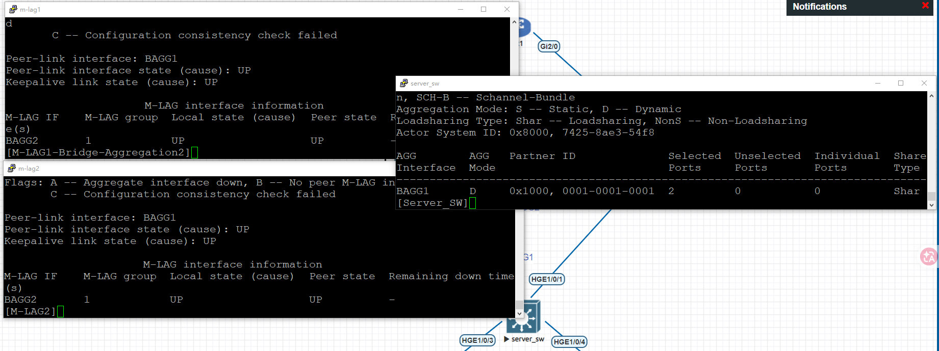
Step 7: Verify M-LAG Status
[SW1]display m-lag summary
Flags: A -- Aggregate interface down, B -- No peer M-LAG interface configured
        C -- Configuration consistency check failed

Peer-link interface: BAGG1
Peer-link interface state (cause): UP
Keepalive link state (cause): UP
This indicates the M-LAG system is successfully established.
Configure Cross-Device Aggregation to SW3
Step 1: Configure BAGG2 on SW1
[SW1]interfaceBridge-Aggregation 2
[SW1-Bridge-Aggregation1]link-aggregation modedynamic
[SW1]interfaceg1/0/2
[SW1-if-range]port link-aggregation group2
[SW1]interfaceBridge-Aggregation 2
[SW1-Bridge-Aggregation1]port m-lag group1
Step 2: Configure BAGG2 on SW2
[SW2]interfaceBridge-Aggregation 2
[SW2-Bridge-Aggregation1]link-aggregation modedynamic
[SW2]interfaceg1/0/2
[SW2-if-range]port link-aggregation group2
[SW2]interfaceBridge-Aggregation 2
[SW2-Bridge-Aggregation1]port m-lag group1
Step 3: Configure Aggregation on SW3
[SW3]interface Bridge-Aggregation 1
[SW3-Bridge-Aggregation1]link-aggregation mode dynamic
[SW3]interface range g1/0/1 to g1/0/2
[SW3-if-range]port link-aggregation group 1
Step 4: Verify Cross-Device Aggregation
[SW1]display link-aggregation summary
AGG        AGG   Partner ID              Selected  Unselected  Individual  Share
Interface  Mode                          Ports     Ports       Ports       Type
--------------------------------------------------------------------------------
BAGG1      D     0x8000, aa7f-9f6a-0200  2         0           0           Shar
BAGG2      D     0x8000, aa7f-a318-0300  1         0           0           Shar
[SW3]display link-aggregation summary
AGG AGG Partner ID Selected Unselected Individual Share
Interface Mode Ports Ports Ports Type
--------------------------------------------------------------------------------
BAGG1 D 0x1000, 0001-0001-0001 2 0 0 Shar The aggregation should show all ports in Selected state.
Configure VLAN Layer 3 Gateways
Step 1: Create VLAN 10 and VLAN 20
Configure trunk ports between SW1, SW2, and SW3 to allow VLAN 10 and VLAN 20. (Steps omitted)
Step 2: Configure VLAN Interfaces on SW1
[SW1]interface vlan 10
[SW1-Vlan-interface10]mac-address 1-2-1
[SW1-Vlan-interface10]ip address 192.168.1.254 24
[SW1]interface vlan 20
[SW1-Vlan-interface20]mac-address 1-2-2
[SW1-Vlan-interface20]ip address 192.168.2.254 24
Step 3: Configure VLAN Interfaces on SW2
Use identical MAC and IP addresses.
[SW2]interface vlan 10
[SW2-Vlan-interface10]mac-address 1-2-1
[SW2-Vlan-interface10]ip address 192.168.1.254 24
[SW2]interface vlan 20
[SW2-Vlan-interface20]mac-address 1-2-2
[SW2-Vlan-interface20]ip address 192.168.2.254 24
Configure Uplink Interfaces and OSPF
Configure IP addresses on uplinks of SW1 and SW2.
Configure IP on R1. (Steps omitted)
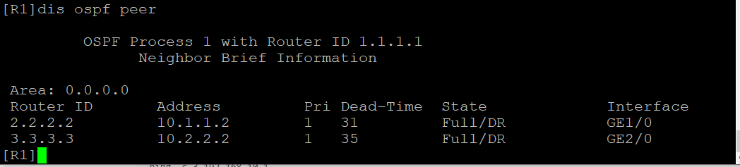
Configure OSPF on SW1, SW2, and R1 to ensure routing connectivity.
Verification Test
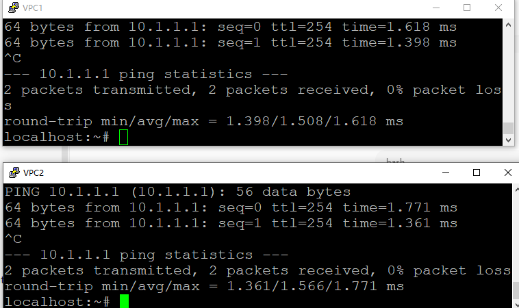
Test connectivity from PC:
<H3C>ping 192.168.1.254
Ping 192.168.1.254 (192.168.1.254): 56 data bytes, press CTRL_C to break
56 bytes from 192.168.1.254: icmp_seq=0 ttl=255 time=1.000 ms
56 bytes from 192.168.1.254: icmp_seq=1 ttl=255 time=1.000 ms
56 bytes from 192.168.1.254: icmp_seq=2 ttl=255 time=1.000 ms
56 bytes from 192.168.1.254: icmp_seq=3 ttl=255 time=0.000 ms
56 bytes from 192.168.1.254: icmp_seq=4 ttl=255 time=1.000 ms
Gateway reachable.
<H3C>ping 10.1.1.1
Ping 10.1.1.1 (10.1.1.1): 56 data bytes, press CTRL_C to break
56 bytes from 10.1.1.1: icmp_seq=0 ttl=254 time=2.000 ms
56 bytes from 10.1.1.1: icmp_seq=1 ttl=254 time=1.000 ms
56 bytes from 10.1.1.1: icmp_seq=2 ttl=254 time=1.000 ms
56 bytes from 10.1.1.1: icmp_seq=3 ttl=254 time=1.000 ms
56 bytes from 10.1.1.1: icmp_seq=4 ttl=254 time=1.000 ms
R1 reachable.
Packet Capture Analysis of M-LAG
To better understand how M-LAG operates internally, packet capture can be performed on the Keepalive interface and the Peer-link interface.
1. Keepalive Packet Capture Analysis
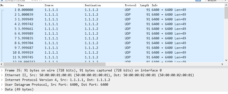
If packet capture is performed on the Keepalive interface (G1/0/1 between SW1 and SW2), the following behavior can be observed:
- SW1 (1.1.1.1) continuously sends UDP packets to SW2 (1.1.1.2)
- SW2 (1.1.1.2) continuously sends UDP packets to SW1 (1.1.1.1)
- The packets are transmitted periodically
- The protocol used is UDP
This traffic represents the M-LAG Keepalive mechanism.
2. Peer-Link Packet Capture Analysis
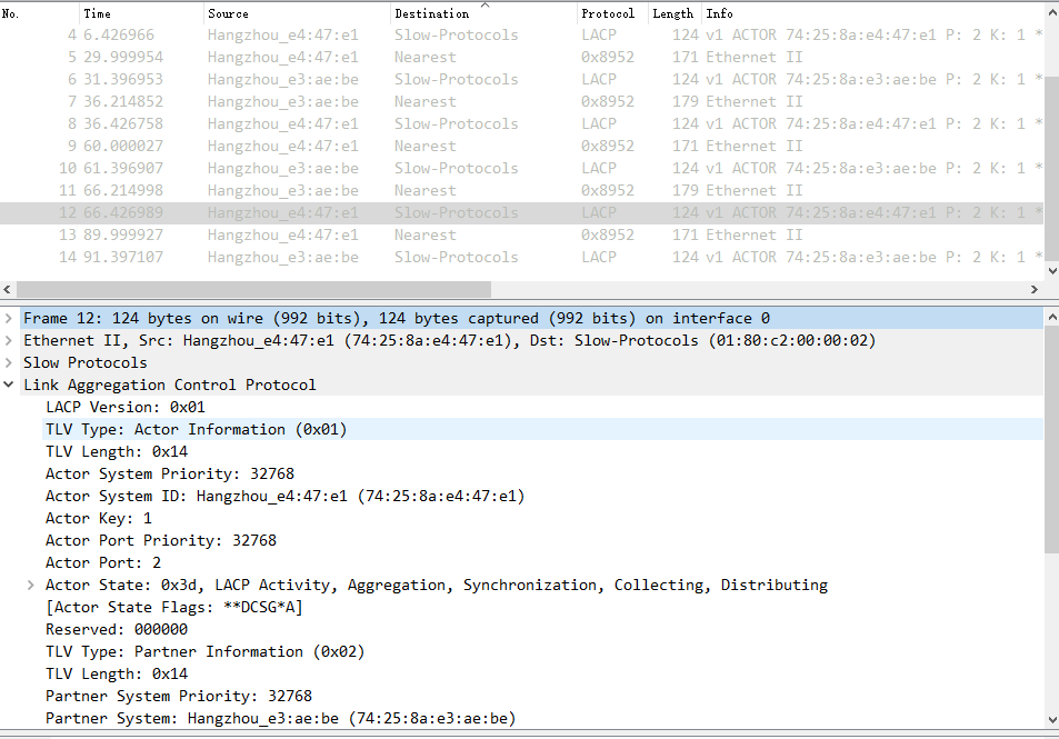
If packet capture is performed on the Peer-link (Bridge-Aggregation 1 between SW1 and SW2), the following types of frames can be observed:
(1) Slow Protocol Frames
- EtherType: 0x8809
- Protocol subtype: LACP or related control protocol
- Used for link aggregation control
(2) Nearest Bridge MAC Frames
01:80:C2:00:00:00
01:80:C2:00:00:02
These are link-local control frames, often referred to as "Nearest Bridge" frames.
They are used for:
STP / PVST
LLDP
LACP
Other Layer 2 control-plane synchronization
Key Technical Insight
M-LAG relies on two independent mechanisms:
- Keepalive (Layer 3, UDP-based)
Ensures peer device liveliness detection.
- Peer-link (Layer 2 control-plane synchronization)
Ensures:
- MAC table synchronization
- ARP synchronization
- Aggregation state synchronization
- Control-plane protocol exchange
This dual mechanism guarantees high availability and loop prevention.