VRRP + MSTP Lab Case
Vrrp+MSTP Lab Case
1. VRRP Experiment
1.1 Experimental Topology
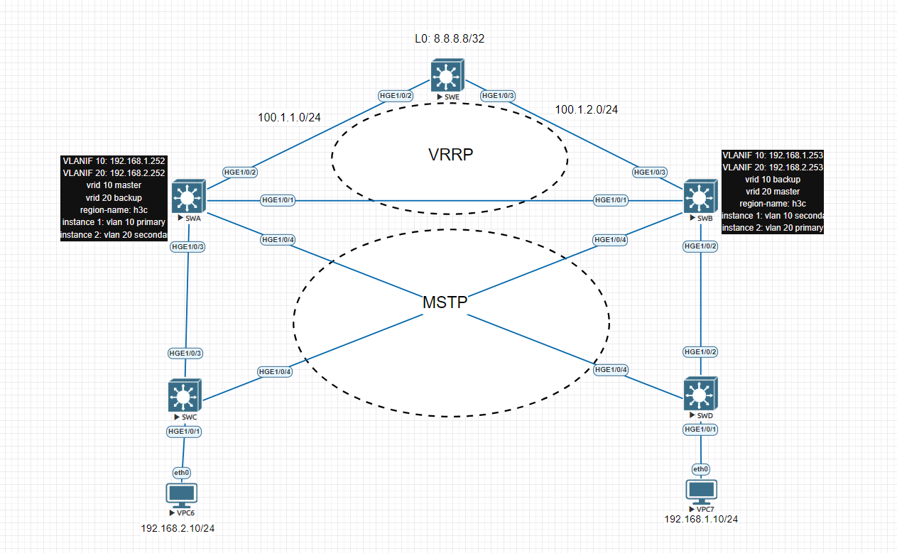
Figure 1-1 Topology Overview
Notes:
- Unless otherwise specified, SWA corresponds to the device labeled
Ain the topology, and SWB corresponds to the device labeledB.
- In the same subnet, the host ID of the IP address corresponds to the device number.
For example, if SWA is in subnet 192.168.1.0/24, its IP address is 192.168.1.252, SWB is 192.168.1.253, etc.
- VLAN10 subnet:
192.168.1.0/24
- VLAN20 subnet:
192.168.2.0/24
- Virtual gateway:
- VLAN10 ->
192.168.1.254
- VLAN20 ->
192.168.2.254
1.2 Experimental Requirements
- Configure IP addresses and gateways according to the topology.
- Create VLAN10 and VLAN20 on SWA, SWB, SWC, and SWD.
- All inter-switch links should allow VLAN10 and VLAN20 to pass.
- Configure VRRP on SWA and SWB:
- SWA acts as the Master gateway for VLAN10.
- SWB acts as the Master gateway for VLAN20.
- SWA and SWB act as backups for each other.
- Configure uplink interface tracking:
- If the uplink fails, VRRP role switching must be triggered automatically.
In addition to VRRP, MSTP is deployed among SWA, SWB, SWC, and SWD.
The MSTP design is as follows:
| MSTP Instance | VLAN Mapping | Root Bridge |
|---|---|---|
| Instance 1 | VLAN10 | SWA (Primary) |
| Instance 2 | VLAN20 | SWB (Primary) |
- SWA is Instance 1 primary, Instance 2 secondary
- SWB is Instance 2 primary, Instance 1 secondary
- All devices belong to the same MST region:
- Region name:
h3c
- Revision-level:
0
This ensures that all switches are part of the same MST region and share consistent instance calculations.
1.3 Configuration Steps
1.3.1 IP Address Configuration
(Omitted for brevity - configured according to topology plan.)
1.3.2 VLAN and Trunk Configuration
(Omitted for brevity - ensure VLAN10 and VLAN20 are allowed on all inter-switch trunk links.)
1.4 VRRP Configuration
1.4.1 Design Analysis
According to the requirement:
- SWA must be the Master for VLAN10.
- SWB must be the Master for VLAN20.
- Default VRRP priority is 100.
- Therefore:
- SWA priority in VLAN10 must be greater than 100.
- SWB priority in VLAN20 must be greater than 100.
- Virtual IPs:
- VLAN10 ->
192.168.1.254
- VLAN20 ->
192.168.2.254
1.4.2 Configuration on SWA
Configure SWA as Master for VLAN10 and Backup for VLAN20.
[SW-A]interface Vlan-interface10
 ip address 192.168.1.252 255.255.255.0
 vrrp vrid 10 virtual-ip 192.168.1.254
 vrrp vrid 10 priority 120

[SW-A]interface Vlan-interface20
 ip address 192.168.2.252 255.255.255.0
 vrrp vrid 20 virtual-ip 192.168.2.254
1.4.3 Configuration on SWB
Configure SWB as Master for VLAN20 and Backup for VLAN10.
[SW-B]interface Vlan-interface10
 ip address 192.168.1.253 255.255.255.0
 vrrp vrid 10 virtual-ip 192.168.1.254

[SW-B]interface Vlan-interface20
 ip address 192.168.2.253 255.255.255.0
 vrrp vrid 20 virtual-ip 192.168.2.254
 vrrp vrid 20 priority 120
1.5 Verification - Normal State
Check VRRP status on both switches.
[SW-A]display vrrp

[SW-B]display vrrp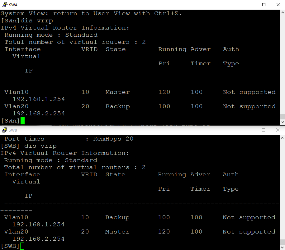
Expected output for SWA:
- VLAN10 -> Master (priority 120)
- VLAN20 -> Backup (priority 100)
Expected output for SWB:
- VLAN10 -> Backup (priority 100)
- VLAN20 -> Master (priority 120)
This confirms that the load-sharing gateway design works correctly.
1.6 VRRP Interface Tracking (Failure Detection)
1.6.1 Design Analysis
By default, interface failure does not automatically trigger VRRP switching.
Therefore, we configure:
- Interface tracking
- Priority reduction when uplink fails
Current priorities:
| Device | VLAN | Priority |
|---|---|---|
| SWA | VLAN10 | 120 |
| SWB | VLAN10 | 100 |
To trigger failover, priority must drop below 100.
So we configure:
priority reduced30120 - 30 = 90 -> lower than 100 -> role switches.
1.6.2 Configure Tracking on SWA
Track uplink interface GE1/0/2.
[SW-A]track 1 interface GigabitEthernet1/0/2

[SW-A]interface Vlan-interface10
 vrrp vrid 10 track 1 priority reduced 30
1.6.3 Configure Tracking on SWB
Track uplink interface GE1/0/3.
[SW-B]track 1 interface GigabitEthernet1/0/3

[SW-B]interface Vlan-interface20
 vrrp vrid 20 track 1 priority reduced 30
VRRP Track Function
The track function monitors a physical interface state.
If the tracked interface fails:
- VRRP priority is reduced
- This may trigger Master/Backup switchover
This allows gateway failover to follow uplink status, preventing traffic blackholing.
1.7 Failure Test
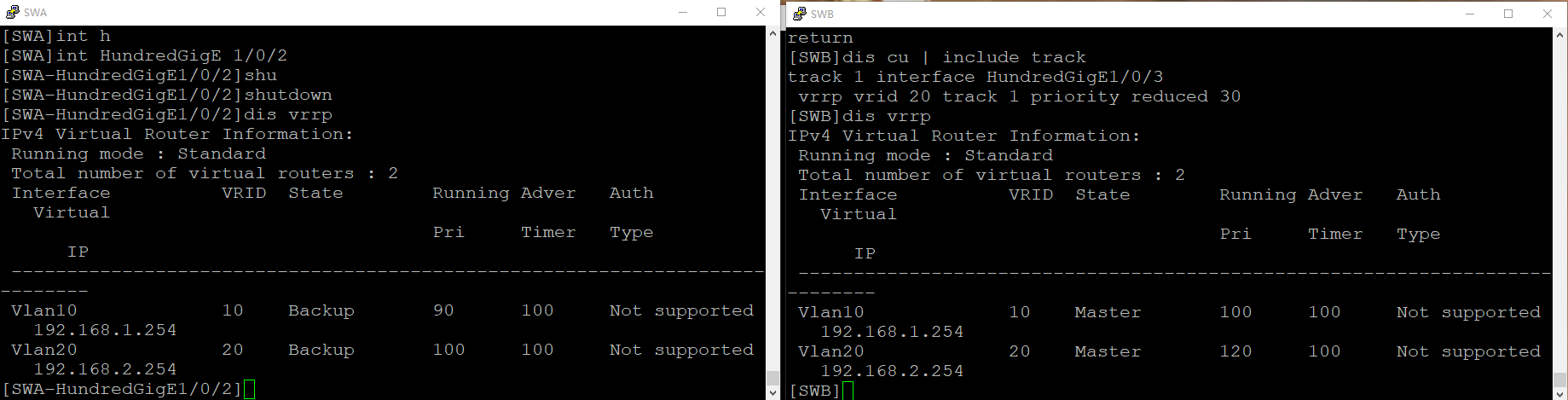
1.7.1 Simulate Uplink Failure on SWA
[SW-A]interface GigabitEthernet1/0/2
 shutdown
Check VRRP status:
[SW-A]display vrrpExpected:
- VLAN10 priority drops to 90
- VLAN10 state becomes Backup
Check SWB:
[SW-B]display vrrpExpected:
- VLAN10 becomes Master
1.7.2 Recovery Test
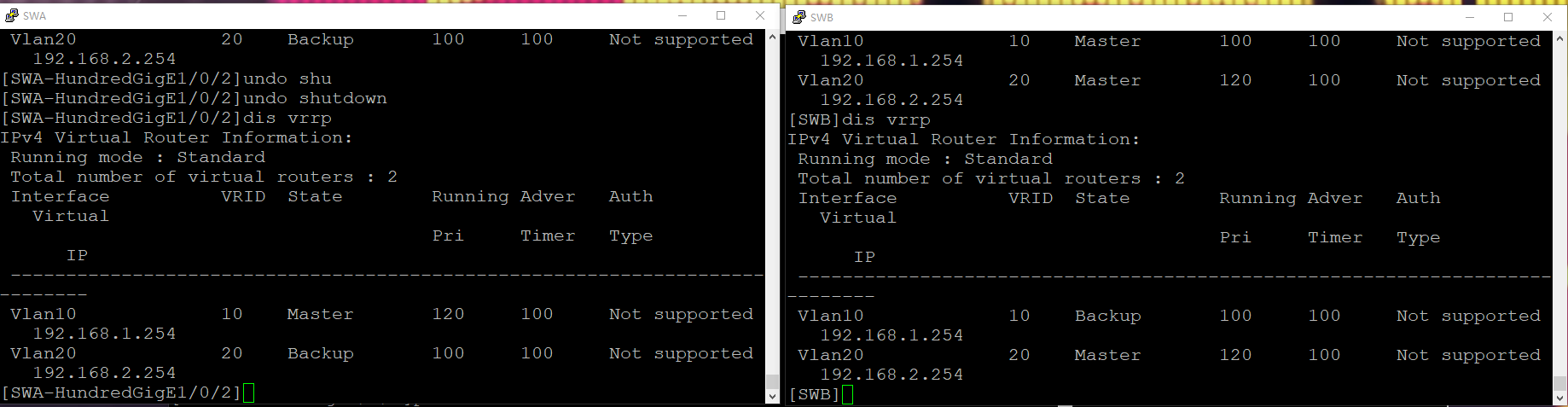
Bring interface back:
[SW-A]interface GigabitEthernet1/0/2
 undo shutdown
If preemption is enabled (default behavior), SWA will regain Master role for VLAN10.
2. MSTP Configuration
2.1 Design Objective
Without MSTP:
- One physical redundant link may be fully discarded
- Only one path forwards traffic
- The other path carries no traffic -> bandwidth waste
With MSTP:
- Different VLANs map to different instances
- Each instance can have a different root
- A port may be:
- Discarding in Instance 1
- Forwarding in Instance 2
This achieves Layer 2 load balancing.
2.2 MSTP Configuration on SWA
SWA:
- Instance 1 -> Primary root
- Instance 2 -> Secondary root
[SW-A]stp globalenable

[SW-A]stp region-configuration
 region-name h3c
 revision-level 0
 instance 1 vlan 10
 instance 2 vlan 20
 active region-configuration
 quit

[SW-A]stp instance 1 root primary
[SW-A]stp instance 2 root secondary
2.3 MSTP Configuration on SWB
SWB:
- Instance 2 -> Primary root
- Instance 1 -> Secondary root
[SW-B]stp globalenable

[SW-B]stp region-configuration
 region-name h3c
 revision-level 0
 instance 1 vlan 10
 instance 2 vlan 20
 active region-configuration
 quit

[SW-B]stp instance 1 root secondary
[SW-B]stp instance 2 root primary
2.4 MSTP Configuration on SWC and SWD
Access switches only need to:
- Enable MSTP
- Join the same region
- Map VLANs to instances
They do NOT configure primary/secondary root.
[SW-C]stp globalenable
[SW-C]stp region-configuration
 region-name h3c
 revision-level 0
 instance 1 vlan 10
 instance 2 vlan 20
 active region-configuration
 quit
Same configuration on SWD.
2.5 Trunk and Access Port Configuration
Inter-switch Links (SWA-SWB-SWC-SWD)
All interconnection interfaces must be trunk:
port link-type trunk
port trunk permit vlan all
undo port trunk permit vlan 1
stp edged-port
Access Ports
- SWC downlink -> VLAN20
- SWD downlink -> VLAN10
[SW-C]interface GigabitEthernet1/0/1
 port link-type access
 port access vlan 20
[SW-D]interface GigabitEthernet1/0/1
port link-type access
port access vlan 103. MSTP Verification
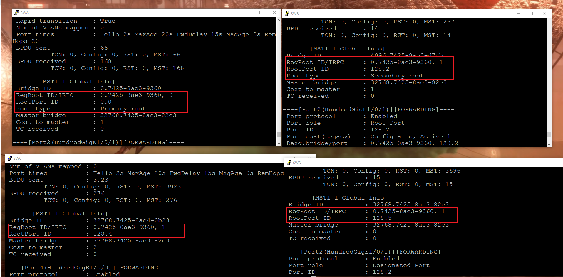
3.1 Check MSTP State - Instance 1
On SWA:
display stpExpected on instance 1:
- Root type: Primary root
On SWB:
- Root type: Secondary root
On SWC / SWD:
- RootPort selected toward SWA
3.2 Check MSTP State - Instance 2
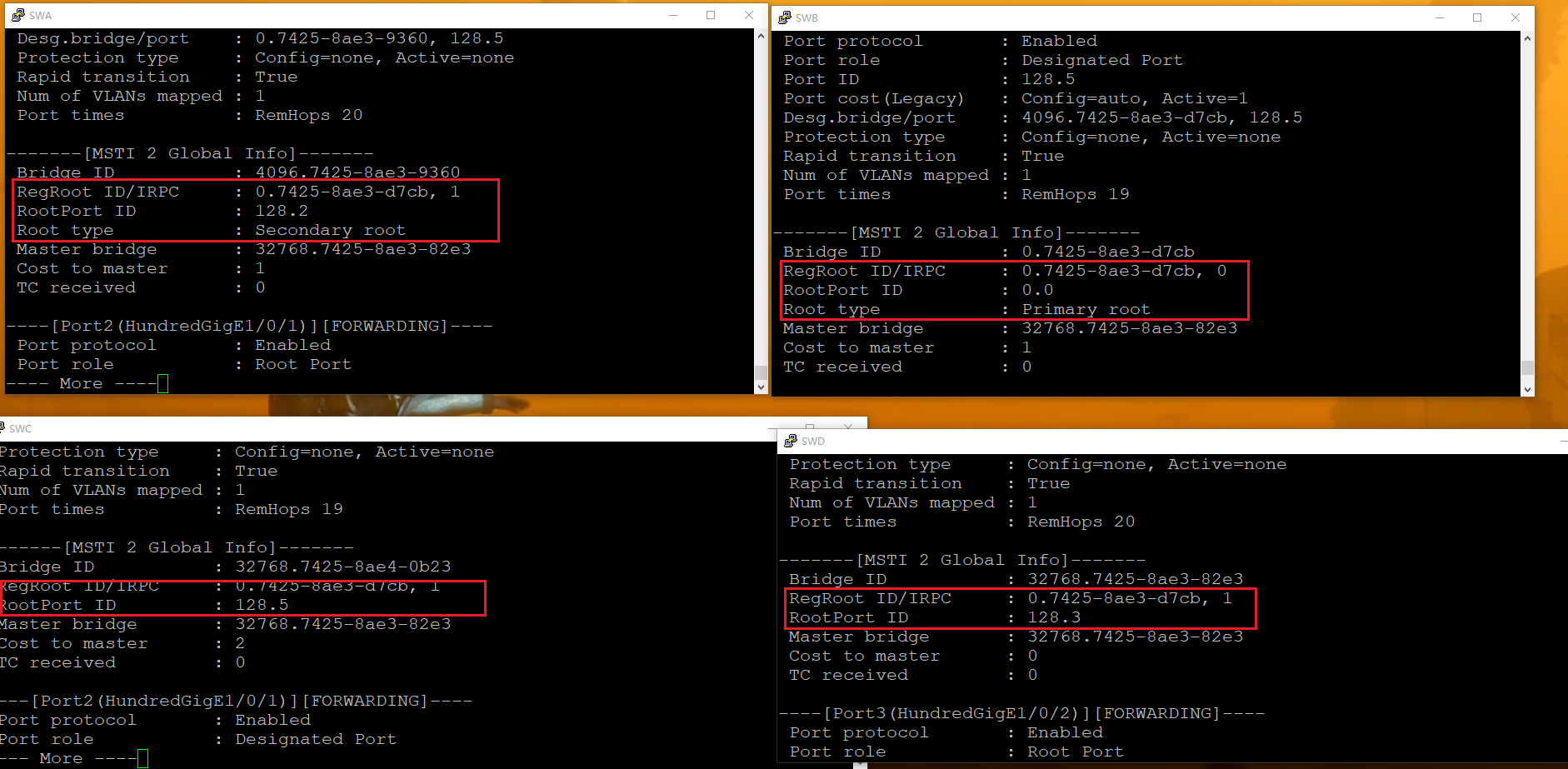
On SWB:
display stpExpected on instance 2:
- Root type: Primary root
On SWA:
- Secondary root
On SWC:
You can observe:
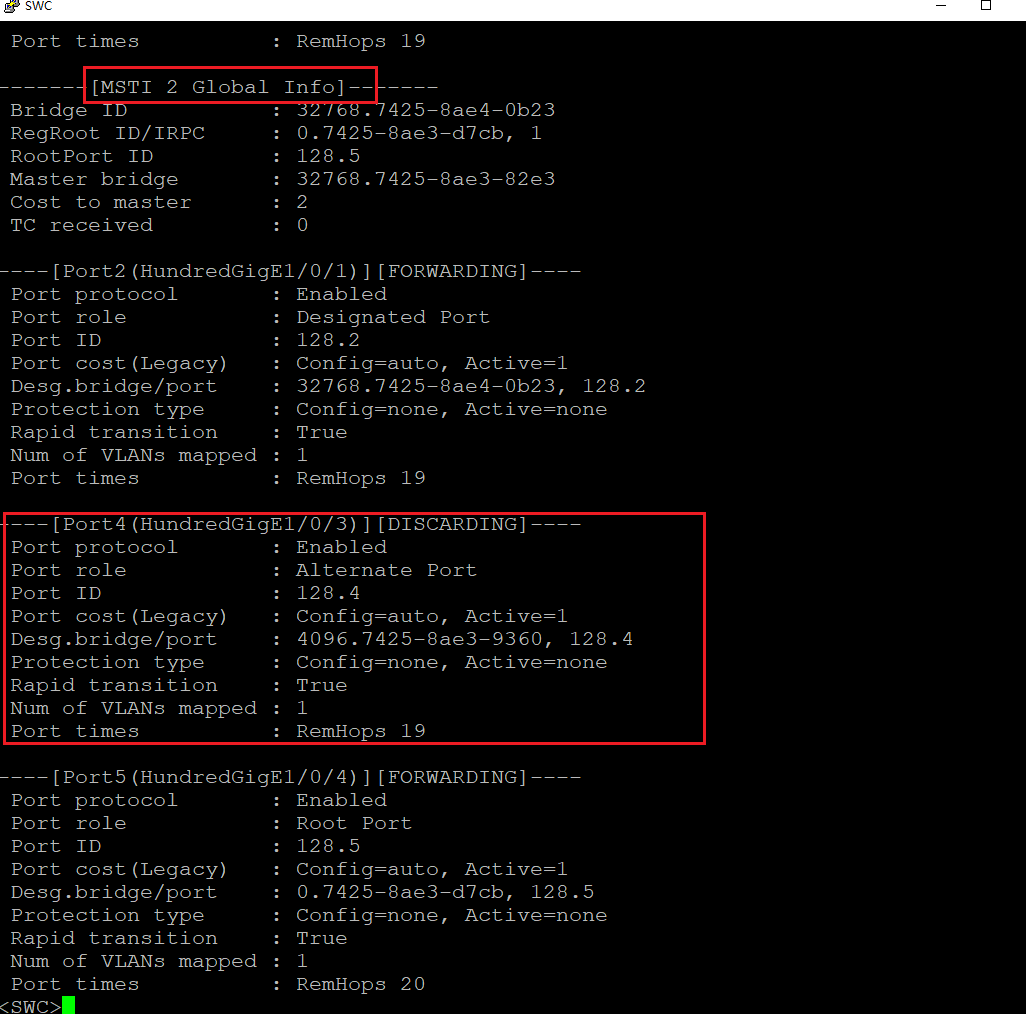
- One interface is DISCARDING in MSTI 2
- Another interface is forwarding
Notice:
In MSTI 2:
Port4 (HGE1/0/3) -> DISCARDING (Alternate)But in MSTI 1:
The same physical link may be Forwarding.
This proves:
鉁?Load balancing across VLANs
鉁?No link is permanently wasted
4. Traffic Verification
4.1 Configure VPC
On VPC6 (VLAN20 side):
ip 192.168.2.10 255.255.255.0 192.168.2.254Ping Loopback0 on SWE:
ping 8.8.8.8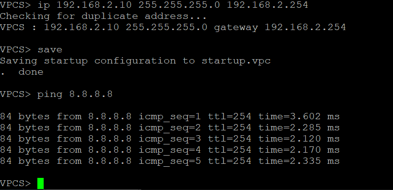
Ping successful.
4.2 Packet Capture Analysis
Capture traffic on SWC.
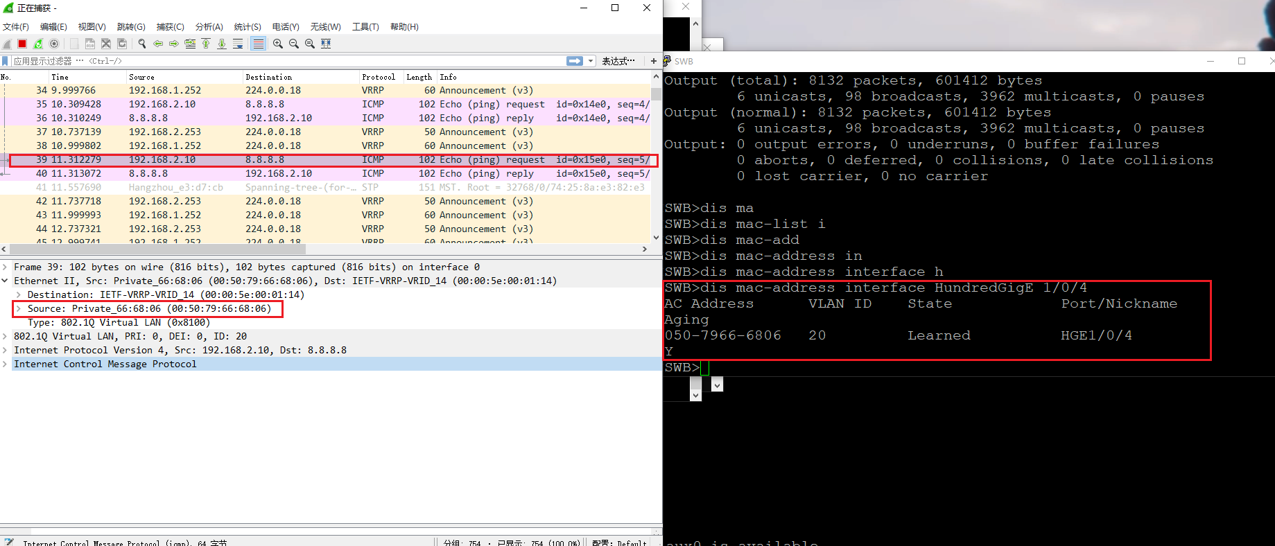
Observation:
Traffic path:
VPC6
-> SWC
-> HGE1/0/4
-> SWB
-> SWE
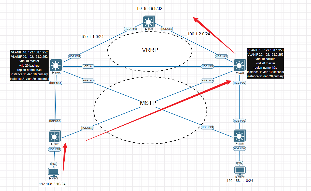
Now verify SWC MSTP table:
display stpYou can observe:
- HGE1/0/3 is DISCARDING in MSTI 2
- HGE1/0/4 is Root Port (Forwarding)
This confirms:
VLAN20 traffic uses the SWB path as designed.
5. Why MSTP and VRRP Are Often Used Together
VRRP provides:
- Gateway redundancy
- Active/standby failover
- Load sharing at Layer 3
MSTP provides:
- Layer 2 loop prevention
- Per-VLAN load balancing
- Efficient utilization of redundant links
Together they achieve:
- High availability
- Gateway redundancy
- Link load balancing
- No bandwidth waste
- Clean and predictable traffic engineering
This is why in enterprise campus networks,
MSTP + VRRP is a very common combination.